
3D design in plant engineering
A powder plant is a three-dimensional problem solved on two-dimensional drawings for most of the last century. That mismatch is where the site surprises came from.
In short
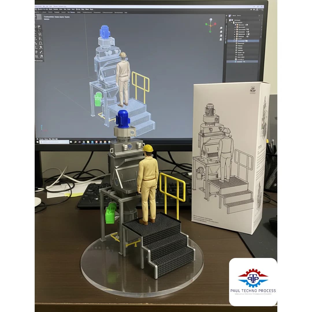
3D design in plant engineering means modelling the whole process plant — equipment, pipework, ducting, structure and services — as a single geometric model before fabrication. It allows clashes, access problems and routing errors to be found and fixed in the model, and produces fabrication and installation information that matches the real site.
The problem 3D modelling solves
A bulk handling plant packs equipment, conveying lines, extraction ducts, structural steel, cable routes and services into a building that is usually too small for all of it. On separate 2D drawings, each discipline can be individually correct while the assembly is impossible. The duct passes through the beam, the valve actuator cannot be reached, the silo outlet is 200 mm off the screw inlet.
Traditionally these were found on site, by fabricators and fitters, and fixed with a grinder and improvisation. Every one of those fixes costs schedule, costs quality, and leaves the plant slightly different from its drawings — which then makes the next modification harder.
A single 3D model removes the ambiguity because there is only one geometry. If two things occupy the same space, the model says so, and it says so months before steel is cut.
Clash detection and access planning
Clash detection is the obvious return. Running an automated check across equipment, pipework, ducting, structure and services finds hard clashes exhaustively, and it finds them at a stage where the fix is a mouse movement rather than a site instruction. In congested powder plants, extraction ducting and conveying lines are the usual culprits, because both are large, both want the shortest route and both are designed late.
The less obvious return is soft clash — the space that has to be empty for the plant to be operable. A valve needs its actuator stroke. A filter needs cartridge withdrawal room. A motor needs to come off its base without dismantling a walkway. A big bag needs crane clearance above the unloader. Modelling those envelopes turns maintainability from something discovered at the first service into something specified in the design.
Operator access is the same argument at human scale. Walking the model at eye height shows where a hose connection is at shoulder height above a running conveyor, where a sample point needs a step, and where a bag tipping station forces an operator into a bad posture on every sack.
From model to fabrication
Once the geometry is settled, the model becomes the source of the manufacturing information. Isometrics, spool drawings, cut lengths, duct development, structural connections and bolt lists all come out of the same dataset, so they are consistent with each other by construction rather than by cross-checking.
That accuracy is what makes off-site prefabrication viable. Pipework and ducting fabricated to modelled dimensions arrives fitting, which shifts hours from site — where they are expensive, slow and disruptive to a client's operation — into the workshop, where they are not. In a retrofit inside a running plant, the value of a short site window is often larger than the whole engineering fee.
For brownfield work the model can start from measured reality. Laser scanning or careful survey of an existing plant gives a point cloud to design against, so a new conveying route is drawn around the pipework that is actually there rather than the pipework the old drawings show.
Communication and client sign-off
A model is also the best communication tool in the project. A client's production manager cannot usefully review a P&ID and a set of GA drawings, but they can walk through a model and immediately say that the tipping station is on the wrong side of the aisle or that the forklift cannot get to the pallet position. That feedback arrives while it is still cheap.
The same applies internally. Process, mechanical, electrical and structural work against one geometry, so a change to a silo position propagates visibly to everyone instead of quietly invalidating three other drawings.
It shortens approval too. Reviewing a plant you can see is faster than reviewing a plant you have to assemble mentally from sections, and fewer review cycles is one of the more reliable schedule savings in a process project.
Project management tools around the model
The model handles geometry; the project still needs to be run. Specialised project management tooling keeps the schedule, the equipment register, the document register, the procurement status and the site progress in one place, linked to the same equipment tags the model uses. That link is what makes progress reporting factual instead of optimistic.
It also makes the interfaces manageable. A process plant project has long-lead equipment, imported components, fabrication, civil work and a client shutdown window to hit, and the risk is almost always in the sequence rather than in any single activity. Visible dependencies are what allow a delay in one item to be re-planned rather than absorbed silently until it becomes a site problem.
The end product of both tools together is an as-built record: a model, a document set and a register that match the plant that was actually installed. That record is what makes the next modification an engineering task rather than an archaeological one, and it is the part of a project whose value shows up years after handover.